With over 300 years of engineering experience, Savery designs and manufactures high-quality hydraulic systems tailored to your needs. If you're interested in this product, fill in our contact form, and our team will be in touch.
Contact usTS08-27 Proportional Electrohydraulic Relief Valve (TS08-27)
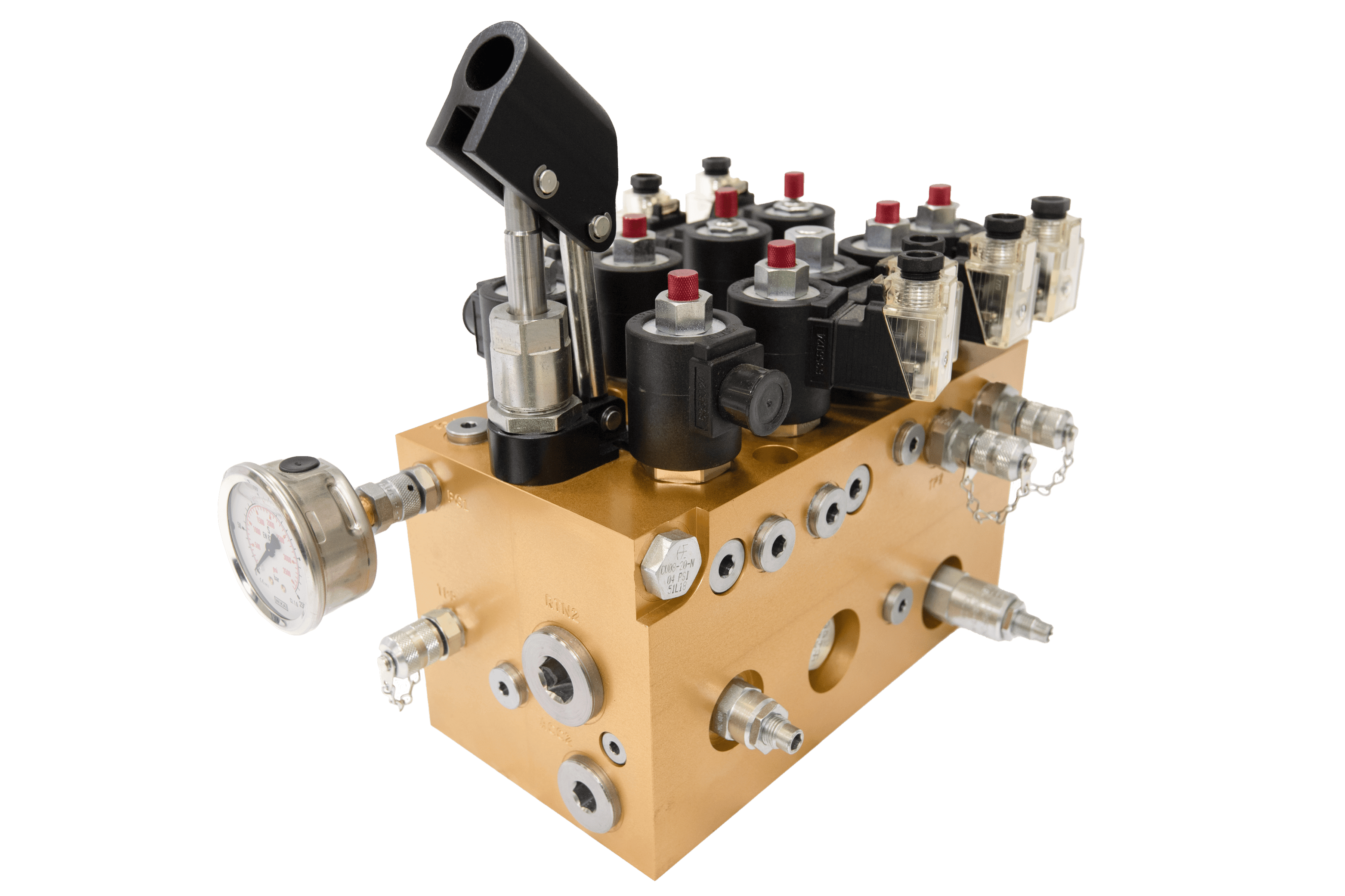
A screw-in, cartridge-style, pilot-operated, spool-type proportional electrohydraulic pressure relief valve, which can be infinitely adjusted across a prescribed range using a variable electric input. Pressure output is inversely proportional to DC current input. This valve is intended for use as a pressure limiting device in demanding applications.
Product Operation
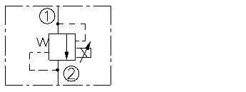
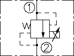
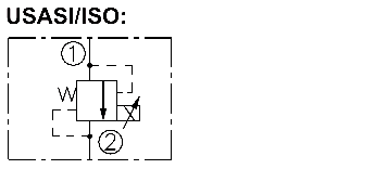
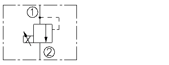
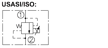
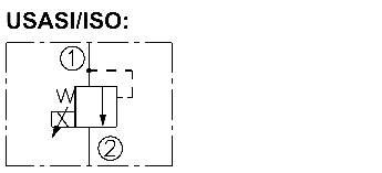
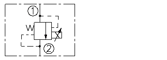
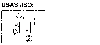
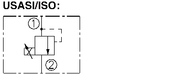
The TS08-27 blocks flow from 1 to 2 until sufficient pressure is present at 1 to open the valve by overcoming the preset induced spring force. With no current applied, the valve will relieve at ±50 psi of the spring maximum. Applying current to the coil reduces the induced spring force thereby reducing the valve setting. The regulated pressure is inversely proportional to the input electrical current.
Note: This valve is ideal for hydraulic fan drive applications. Consult factory for electronic controllers specifically designed for fan drive applications.
Product Features
• 12 and 24 volt coils standard.
• Industry common cavity.
• Hardened parts for long life.
Product Ratings
Maximum Operating Pressure: 241 bar (3500 psi)
Electrical Parameters:
D-Coil
E-Coil
10 VDC 12 VDC 20 VDC 24 VDC 12 VDC
24 VDC
Max Control Current (amperes)1.501.310.850.651.400.70
Resistance (Nominal) (ohms)3.15.412.221.75.421.7
Relief Pressure Range from Zero to Maximum Control Current:
A: 207–6.9 bar (3000–100 psi)
B: 138–6.9 bar (2000–100 psi)
C: 68.9–6.9 bar (1000–100 psi)
Rated Flow: 24.6 lpm/6.5 gpm; P = 13.8-17.2 bar (200-250 psi), cartridge only; port 1 to 2 coil energized
Maximum Pilot Flow: 0.76 lpm (0.2 gpm)
Hysteresis at PWM 200 Hz (% of max pressure): A: 3.2
B: 3.0
C: 4.8
Flow Path: Free Flow: 1 to 2 coil energized; Relieving: 1 to 2 coil de-energized
Pressure Rise: A: 0.48 bar/lpm (26.5 psi/gpm(;
B: 0.36 bar/lpm (20 psi/gpm)
C: 0.46 bar/lpm (25 psi/gpm)
Temperature: -40 to 120°C (-40 to 250°F) with standard Buna N seals
Filtration: See page 9.010.1
Fluids: Mineral-based or synthetics with lubricating properties at viscosities of 7.4 to 420 cSt (50 to 2000 sus); See Temperature and Oil Viscosity, page 9.060.1
Installation Recommendation: When possible, the valve should be mounted below the reservoir oil level. This will maintain oil in the armature preventing trapped air instability. If this is not feasible, mount the valve horizontally for best results.
Cavity: VC08-2; See page 9.108.1;
Cavity Tool: CT08-2XX; See page 8.600.1
Seal Kit: SK08-2X-B; See page 8.650.1
ISO SYMBOL
2.860.1
PERFORMANCE